Monday, August 20, 2018

Picture Frame - a RPiPF on the schedule

The previous builds were smaller but smarter. They actually turned off when nobody was around to see. The RPiPF (RapsberyPi Picture Frame) is not there yet.

A small step forward: turn off when nobody's around to watch and turn on when there may be - on the schedule. Turn on at 7am, turn off 11pm.

To control the TV from RPI - CEC


Consumer Electronics Control (CEC) is a control channel over the HDMI cable.

Install cec-utils

sudo apt-get install cec-utils

Turn the TV off:

echo "standby 0" | cec-client -s -d 1 

Turn the TV on

echo "on 0" | cec-client -s -d 1


Don't mind the CLI plumbing - these command are like magic: '-s' means execute single command while '-d 1' limits the damage to you eyes by cutting down the logging spewed back at ya. Note that the echo just pipes the actual command to the cec-client - an interactive program by birth.

Flying on a Magic Script

The ph.sh script that was previously used to just start feh. Now it does the scheduling.
The script loops and:
  • checks the time
  • decides if the slide show should or should not be running
  • depending on that decision either 
    • kills feh and turns off the TV or 
    • starts feh and turns on the TV
  • sleeps for 1 minute and repeats

logger "PF started"
PATH=$HOME/bin:$PATH
while true; do
  now=`date +%H%M`
  fehpid=`pidof feh`
  if [ $now -gt 700 ] && [ $now -lt 2300 ]; then
    if [ -z $fehpid ]; then
      logger "PF now=$now fehpid=$fehpid ON"
      tvon
      gofeh &
    fi
  else
    if [ ! -z $fehpid ]; then
      logger "PF now=$now fehpid=$fehpid OFF"
      skill feh
      tvoff
    fi
  fi
  sleep 1m 
done

Taking it apart

  • The lines with 'logger ...' just put entries in /var/log/user.log so I know what was happening.
  • The line "PATH=" just adds /home/pi/bin (user's pi bin directory) to the path. Normally this should be done the .profile.
  • Then we loop forever...
  • The line 'now=... ' captures current time into the 'now' variable. The time is formatted as hhmm (in 24 hour format) for easier comparing later.
  • The 'fehpid=...'  captures the process ID of feh, the slide show process. If it is not running, the fehpid is empty string.
  • Then in the first 'if' the script compares the $now to fit between 700 and 2300, military style.
  • And finally, the nested 'ifs' decide to turn on the show or to stop it. The '-z' checks for empty, while the '! -z' checks for not empty.
  • The small command scripts:  tvon, tvoff, gofeh got created in ~/bin (and chmod +x them so they can be executed).
  • The gofeh is run in the background (with '&') so the script can continue monitoring the time after starting the slide show.

References

Monday, July 30, 2018

40" Picture Frame For under $100

Yup, another version of my picture frame obsession (YAPF). I have turned several laptops into picture frames in the past. The Mark I, a ca'95 HP laptop is still running strong, 8 years non stop. The Mark II ca'99 HP laptops were not that strong. These died after few years...something changed in HP's quality about the new millenum...

So here we go again! This time I am spending real $$$ on it!

The ingredients:

  1.  A used HDTV from craigslist.org.  Best, a TV with LED back-light and 1080p resolution (a 720p works too but the picture quality is not that great unless they are small.). I got a 4yr old Emerson LC401EM3F.for $75
  2. Rapsberry Pi Zero $5 or better RPiZeroW $10 (much more fun to access remotely)
  3. miniSD card, greater than 4GB capacity $5
  4. 5V USB power supply (a charger better than 500mA), USB cable (to power RPi) $10
  5. High-Speed Mini-HDMI to HDMI Cable, such as this (Amazon Basic) $5
Total about $95.

Quick steps to the finish

Here are the steps to achive glory in less than an hour...that is if you know what you're doing. (Some skills required.)

Create Bootable Raspian Lite system. 

There are plenty tutorials online how to do it here.
  • Download Raspian Lite (at the time of writing it's STRETCH). Here. 
  • Image your microSD card (on linux I use dd)
  • Connect a keyboard (needs a microUSB to USB cable/adapter, OTG works) to USB port.
  • Connect monitor via you cable (you can use adapters but the connectors on RPIW are fragile and close together so cable work better).
  • Power it up by plugging the USB charger/power supply into PWR connector.
  • You should see RPI booting.
  • After booting, log in as pi, password raspberry

Configure the system, via raspi-config utility.

  • change password (if you want)
  • set hostname (if you want)
  • configure wifi (so you can log into it with ssh - applies only to RPIZ or if you plug inWiFi adaptor)
  • enable ssh
  • configure locale: US UTF-8, timezone
  • configure keyboard: Generic 104 PC, US than at the end there is option to set Ctrl-Alt-Backspace to kill X
  • configure boot to console (not graphical)
  • set to resize file system to full CD
  • reboot, check that wifi is connected (ping something), also check you can ssh to the system (handy later)

Add to the system, as Lite is a bit...lite.

  • first update  all
    • sudo apt-get update && sudo apt-get upgrade -y
  • reboot 
  • install graphical display (xorg) and other utils
    • sudo apt-get install --no-install-recommends xserver-xorg xinit x11-xserver-utils lightdm feh
    • note: the lightdm allows auto login to X; feh is the slide show application.

Configure scripts so things start automatically on every boot.

  • create ~/.xinitrc (this is what startx runs: disable x screen blanking and make it execute pf.sh at the end)
    xset s off
    xset -dpms
    xset s noblank
    /home/pi/bin/pf.sh
  • create ~/bin/pf.sh to start feh in desired mode - full screen, randomized slide show 60s, no mouse etc and make it look for pictures in ... Pictures directory)
    feh -xrzYZFD60 --no-pointer --auto-rotate ~/Pictures
  • in ~/.profile add the following at the end  (this runs startx on login from tty1 so autologin will use it)
    if [[ -z $DISPLAY ]] && [[ $(tty) = /dev/tty1 ]]; then
    startx
    fi

Enjoy the view

Put some pictures in Pictures directory (you can use the scp utility via network).
Connect da TV.
Reboot.
You should see RPI booting and then switching into graphical X and after a moment displaying the pictures.

DONE?


Ahh...No....not completely. I still want the YAPF.M3 to turn off when nobody is watching and back on when somebody is here (via a PIR sensor). More on this later  (hooking PIR sensor, using HDMI CEC TV control and wrapping it all in a script).

Here is how to add schedule to the YAPF.M3
http://minkbot.blogspot.com/2018/08/picture-frame-rpipf-on-schedule.html

Also, since it's already connected to wifi, perhaps it could suck in the pictures itself? The disadvantage is that I am still using Picassa and which do not modify my pictures (Picassa just remembers the operations) and the pictures would be the resolution unnecessary higher than 1080p (20MP anyone?).

Github Repository

All the files are in github. These can be copied to the home directory: ~/home/pi.
https://github.com/michkrom/pictureframe


Saturday, July 28, 2018

Google Assistant Marine Weatherman

Once upon a time, I decided that checking  the weather on the phone while driving is not conducive to safety.  But then I learnt about Google Assistant AI thingy that is changing the world...sorry Alexa!
And here is a story of trying to build a Google Assistant skill for accessing marine weather information.

WHY

Soo...what marine whether data am I interested in? Wind, tides, fog, swell....I am a kite-surfer and my day-to-day ability to kite depends on catching the windy days. I need to know! Since I am on north California coast I depend on NOAA and NWS.

WHAT

So here are some web weather resources I want to access via a speach-based application:

Coastal Forecasts
http://tgftp.nws.noaa.gov/data/forecasts/marine/coastal/
Tide Predictions
https://tidesandcurrents.noaa.gov/tide_predictions.html
Noaa Buoys:
https://www.ndbc.noaa.gov/mini_station_page.php?station=44017

HOW

Google Assistant AI. Well...really the AI?...That depends on your definition of 'I'.  IMHO, it is not AI - it is a speech-to-text (a very good one, mind you) then a text pattern matching filter with ability to invoke external web servers when matched a pre-canned pattern.  It can't think by itself (the 'I' in AI is rather weak).

LINGO


Here is the lingo, which took me quite a time to decipher:

Google Assistant

A user facing system that can accept user input and provide, by some magic means, relevant output. Google Assistant (GA) has a plethora of 'native skill' and ability to invoke 3rd party applications (via 'talk to XYX'). There is also notion of Actions on google..I think it's just a fancy name for an Google Asistant application?

Google Assistant Application

(aka skill...aka Action?) It is what I have created. GA apps are invoked by 'talk to XYZ', in my case it is 'talk to marine weather'. I tried to be funny but GA app name must be 2 or more words so Neptune or Poseidon did not work.

DialogFlow

Is a text pattern matching system - my application (my Google Action) is a set of text patterns, aka Intentions (read: 'user intentions', 'user statements').
(I suspect there is a close relation between defined patterns and a speech recognition as each time I update the pattern it says it's 'training...', likely speech recognition is much better if the correlator knows what to expect). DF also contain a system of describing parameters (ie the variables in intentions) via Entities and also linking intention to external web-based services (aka Fulfilment).

DialogFlow Intentions

I have mentioned the intentions. These are the patterns that constitute one user desire (intention) and DF app may have many intentions. In intention, the same thing may be expressed many different ways:
tides for bodega
give me tides for bodega 
what are the tides for bodega
bodega tides
give me bodega tides
etc..
Intentions can have parameters here a 'location' would be a parameter. One can select a part of the example sentence and make it a parameter. So:
tides for 'LOCATION'
where location is a parameter. Which brings us to entities.

DialogFlow Entity

Entity is a ... type (specification) of a parameter.  You can use predefined entity (such as 'city' 'time' 'color' etc) or define your own or ... use @sys.any which is ...well anything.

DialogFlow Fulfilment

Simple intention can have canned responses. You define them right in the dialog flow. But if you need to go to get some real time data, the fulfillment is where things get more interested. Fulfillment is essentially the GA/DF reaching to some other place in the WWW and getting a reply. So fulfillment is a www server accepting a https request returning a response. The request and response are GA-specific, JSON formatted collection of parameters. You can host this service yourself or you can use google services. The google services are called Firebase. Note, the Google Firebase is more generic than focused on GA/DF but there is a good support to make things easy.

It's all pretty convoluted and overwhelming on the first date...

Monday, July 9, 2018

It's been a while

Yup, I got busy/lazy/having too much fun. This post is just to unplug the pipes, move the joints and warm up my fingers...

Thing I have been toying with:
  • Picture Frame Mark2
  • Ghost-busters backpack (Halloween Outfit)
  • Fulling around with MSP430
  • Fulling around with rPIs (3,zero,zerow)
  • Fulling around with MSP8266
  • Lego robotics help training
  • Odyssey of the Mind training
  • Hacking Ikea ANSLUTA remote
  • Building and flying quads and fix wings RC
  • Flying man-lifting kites in the waves.
  • Sailing sailing boats
  • Remodeling
  • Life
My current toyject (short for toy-project): Google Assistant app for Marine Weather.

Stay put, some of these will find it's way here.

Sunday, March 8, 2015

FS-T6 firmware upgrade

As we are working on FS-T6 custom FW (called AR-T6) we are trying to provide an easy path for early adaptors. Here is how to program the AR-T6 firmware  into your Tx or revert to the original. Both without opening the case.


What is needed:
- stm32flash utility (can be build on linux and windows) or a STM loader demonstrator
- compiled ar-t6.bin or original fs-t6.bin fw
- serial port or usb-to-serial adapter
- some means to connect adapter's leads to the port on FS-T6
- some knowledge of cmd line on linux


Connections:
BLACK - GND to the S-Video ring
WHITE - PC Rx to T6's Tx
GREEN - PC Tx to T6's Rx
(see: student cable for connections)

Note that to get a good grounding I had to bend the pin of black ground wire and wedged it into the space.
Also note that the connection is potentially very flaky and may soft-brick your Tx if interrupted in the middle (recovery possible but only with an SWD cable). A safer way would be to use a CT6B cable or to make a custom cable from an S-Video one...as described here)


Linux

check connection:

~/stm32flash$ sudo ./stm32flash /dev/ttyUSB0
stm32flash 0.4

http://stm32flash.googlecode.com/

Interface serial_posix: 57600 8E1
Version      : 0x22
Option 1     : 0x00
Option 2     : 0x00
Device ID    : 0x0420 (Medium-density VL)
- RAM        : 8KiB  (512b reserved by bootloader)
- Flash      : 128KiB (sector size: 4x1024)
- Option RAM : 16b
- System RAM : 2KiB


To program custom fw:
~/stm32flash$ sudo ./stm32flash -w ar-t6.bin -v /dev/ttyUSB0
stm32flash 0.4

http://stm32flash.googlecode.com/

Using Parser : Raw BINARY
Interface serial_posix: 57600 8E1
Version      : 0x22
Option 1     : 0x00
Option 2     : 0x00
Device ID    : 0x0420 (Medium-density VL)
- RAM        : 8KiB  (512b reserved by bootloader)
- Flash      : 128KiB (sector size: 4x1024)
- Option RAM : 16b
- System RAM : 2KiB
Write to memory
Erasing memory
Wrote and verified address 0x0800f178 (100.00%) Done.


To program custom fw:
~/stm32flash$ sudo ./stm32flash -w fs-t6.bin -v /dev/ttyUSB0
...


In Original FW you go to Menu, System, scrol down to "Firmware Upgrade".
In AR-T6 go to Menu, System, Version page, Menu (pres&hold SELect roller).


Thanks go to Martin, here is his writeup.


Sunday, November 23, 2014

FS-T6 student cable


FS-T6 has a build in connector for another radio to be used as a trainer. However, the connector is rather unusual S-VIDEO one.  There is a discussion about making a cable in the rcgroups:
http://www.rcgroups.com/forums/showthread.php?t=1720333&page=4


The connector is on the back of the radio. It has 4 active pins and it uses connector shield for ground.  Using standard s-video (see above wikipedia link) pins the signals on the radio are:
1 - PPM TX
2 - PPM RX
3 - SERIAL TX
4 - SERIAL RX
connector ring - GND

The signals that needed to be connected between the two T6s are #1 and #2 crossed (ie TX of one radio goes to RX of another and vice-versa). I have decided to cross both PPM TX/RX and Serial TX/RX to avoid output shorts...(ie output driver another output).  Maybe one day we find a use for two radios communicating through a serial link? This essentially creates a "null modem" cable.

To make a cable you have 2 choices: 1) buy 2 plain connectors and solder the wires 2) rewire a standard s-video cable. Being a frugal guy I have opted for #2 (s-video cables are available for <$4 while single s-video connectors are more). However, standard S-VIDEO cables do not connect the grounds and connections are straight. Here, to connect two T6s you need to "cross the streams" and add the ground wire.

Start with taking out the outside rubber. I cut the connectors first, Start cutting from the cable side to the connector to avoid cable damage (if you slip the knife). Then pull the rubber off.


Next. Cut the cable in half In order to cross the streams. You may decide to do it in the middle (like I did). Or close to one of the connectors (if you want to wrap it with connector later).
After cutting, unwrapping the shields, stripping the middle wire and re-soldering crossed over, I have wrapped them in electrical insulating tape. Note, the cross over is 1<-->2 and 3<-->4 which are on different cables (connect shield of one cable to center lead of another for each cable.).

Than next I have added the ground wire. I have soldered it directly to the outside metal ring on both ends, then slipped the wire into a groove cut out in the connector plastic.

The finished cable looks rahter nagly (nasty&ugly) but it works. However, the s-video connectors do not make solid mechanical plug. So if your plugs fall out as much as mine you'd want to lead the cable through the radio handles first and then plug it in. 


My son and I flew together last week! It works!

Tuesday, October 28, 2014

FS-T6 and SWD hack


Preparing the FlySky-T6 RC TX for development with SWD. 


SWD = Single Wire Debug

  Well, the SWD at a minimum requires 3 wires: clock, data and ground (great marketing though).  In addition, it is very handy to add a reset line (nSRST_.  This line would reset all the devices around the core CPU in the SoC chip in addition to restarting the CPU core.  Otherwise, starting conditions would differ form run to run and I often see hangs.  I have tried to use the 3 wires (aka ST-LINK V1, as featured on STM32FVLDISCOVERY with CPU similar to the T6's stm32f1xx chip). I did not like it.  Hence later, I have hacked in the 6 pin connector.


STM32F0Discovery

Discovery

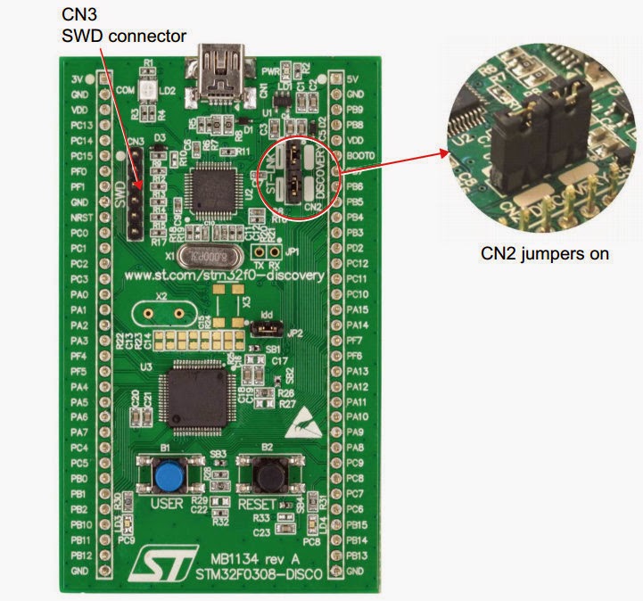
Discovery stm32f1discovery is equipped with 4 pin SWD.  All other discoveries AFAIK are ST-LINK V2 and come with 6 pin SWD.  Remove the jumpers as shown on left to disconnect the on-board SWD control from the CPU (the one that also plugs into your PC's USB; discovery docs) then you can use the SWD connector to pulg it into T6.

Notably, the V1 and V2 also differ in software. and in general the V2 is much more reliable according to openocd references.


4-pin SWD

Schematics

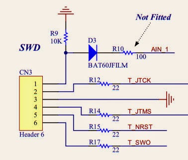
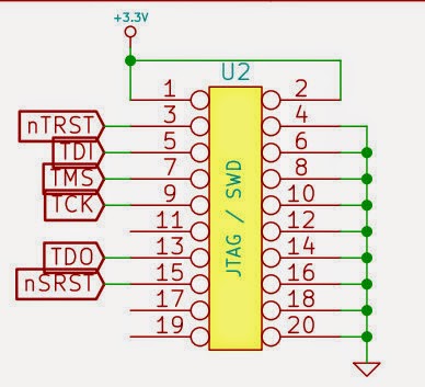
Here are the schematics for 4,6 pin and full 20 pin SWD connector as seen on T6.


Note that SWD lines are also used by JTAG. Through some signaling magic CPUs would cpu obey (switch into) SWD instead of JTAG.


The 4 pin is identical to the first 4 pins on 6-pin connector - handy!.


6-pin SWD
The VDO pin (pin 1 of the connectors) is not used - it is disconnected on discovery boards. I tied it to +3V3 on T6's side.


Connections to T6


T6 20-pin "full" debug connector


I have connected the following:
 U2(T6)    CN3 (DISCO)
+3.3V P1---P1 VDD 
TCK   P9---P2 TCK
GND   P20--P3 GND
TMS   P7---P4 TMS
nSRST P15--P5 NRST
GND   P18--P6 SWO

Also the SWO is not available on F1xx CPU (this is used normally for trace output). This schematics is from ar-t6 .


Here is the final result. Pin #1 is marked with a sqare, left lower row.
I have also cut out small opening for a standard 6-ping header (female) that I have crimped and than hot-glued to the case. So now I can close the T6 and have it ready for flying in no time. Additionally, I found a 12V PS with correct plug and can now power T6 on my desk w/o batteries - this is a bonus and not required.

Let me know.
...sorry for formatting - blogger is a pile of streaming google...and google really stinks recently...