Preparing the FlySky-T6 RC TX for development with SWD.

SWD = Single Wire Debug
Well, the SWD at a minimum requires 3 wires: clock, data and ground (great marketing though). In addition, it is very handy to add a reset line (nSRST_. This line would reset all the devices around the core CPU in the SoC chip in addition to restarting the CPU core. Otherwise, starting conditions would differ form run to run and I often see hangs. I have tried to use the 3 wires (aka ST-LINK V1, as featured on STM32FVLDISCOVERY with CPU similar to the T6's stm32f1xx chip). I did not like it. Hence later, I have hacked in the 6 pin connector.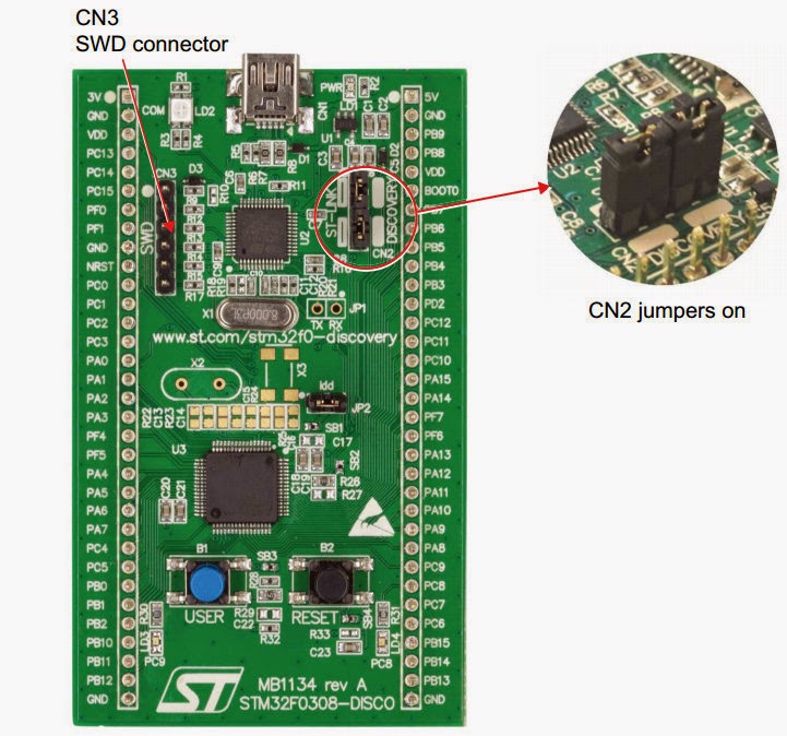 |
| STM32F0Discovery |
Discovery
Discovery stm32f1discovery is equipped with 4 pin SWD. All other discoveries AFAIK are ST-LINK V2 and come with 6 pin SWD. Remove the jumpers as shown on left to disconnect the on-board SWD control from the CPU (the one that also plugs into your PC's USB; discovery docs) then you can use the SWD connector to pulg it into T6.Notably, the V1 and V2 also differ in software. and in general the V2 is much more reliable according to openocd references.
 |
| 4-pin SWD |
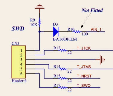
Schematics
Here are the schematics for 4,6 pin and full 20 pin SWD connector as seen on T6.Note that SWD lines are also used by JTAG. Through some signaling magic CPUs would cpu obey (switch into) SWD instead of JTAG.
The 4 pin is identical to the first 4 pins on 6-pin connector - handy!.
 |
| 6-pin SWD |
Connections to T6
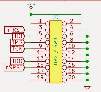 |
| T6 20-pin "full" debug connector |
I have connected the following:
U2(T6) CN3 (DISCO)
+3.3V P1---P1 VDD
TCK P9---P2 TCK
GND P20--P3 GND
TMS P7---P4 TMS
nSRST P15--P5 NRST
GND P18--P6 SWO
Also the SWO is not available on F1xx CPU (this is used normally for trace output). This schematics is from ar-t6 .
 Here is the final result. Pin #1 is marked with a sqare, left lower row.
 I have also cut out small opening for a standard 6-ping header (female) that I have crimped and than hot-glued to the case. So now I can close the T6 and have it ready for flying in no time. Additionally, I found a 12V PS with correct plug and can now power T6 on my desk w/o batteries - this is a bonus and not required.
Let me know.
...sorry for formatting - blogger is a pile of streaming google...and google really stinks recently...
2 comments:
Once you have connected your stm32 to the FST6, how do you flash the firmware?
For development I use the OOCD (http://openocd.sourceforge.net/) this works good enough with Eclipse plugin. Alternatively, for flashing you can use stlink utility (from STM).
However, recently we have adopted a flash-over-serial (using build-in stm bootloader) and stm32flash utility.
See: http://minkbot.blogspot.com/2015/03/fs-t6-firmware-upgrade.html
Post a Comment