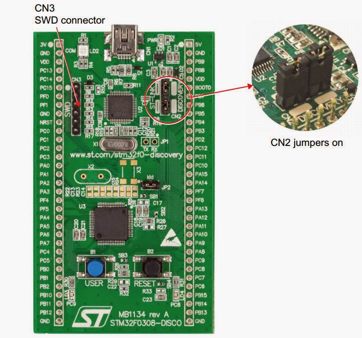
This is a very terse dump of my experience of setting up a development environment for developing software for STM32Fxxx series of ARM processors. These CPUs come in a VERY inexpensive "discovery" boards (e.g. STM32F0DISCOVERY, STM32F3DISCOVERY, STM32F4DISCOVERY) - very fun to toy with (usually $10-20 and no need for any "emulators", "jtags" programmers etc). So this is cheaper then the famous "arduino" and you get a 32bit processor with tons of peripherals. I actually used this to start developing firmware for FlySky-T6 RC transmetter following the fantastic work here.
In order to develop embedded software one usually needs: text editor, build tools, programmer/debugger tools. Here there are in order:
- Eclipse
- gnu arb toolchain
- openocd
The Eclipse is an IDE (Integrated Development Environment) that integrates editor, project management, build, debug documentation in one common, portable, extendable GUI.
The gnu arb tool chain provides compiler/linker/stdlibraries/debugger to produce executable code.
The openocd provides access to hardware. It can communicate with hardware debugger agent and provide flash memory access and debugger server that then can interact with gdb (the gnu tools debugger). An ST-LINK/ST-UTIL (texane or STM versions) can be used instead as well.
Eclipse/GNU/OpenOCD setup
Eclipse:
http://www.eclipse.org/downloads/
this usually ends up a "java" development without CDT ("C/C++"). I have downloaded Eclipse "Luna" .
Install CDT Plugin (skip this if you've donwloaded a CDT-Eclipse):
http://www.eclipse.org/cdt/downloads.php
in the above find correct "p2 repository" link --> Copy to clipboard
in eclipse: Windows->Install New Software->Paste Link
install main CDT + GCC and HW debug
Install GNU ARM Plugin
install "p2 repository":
http://gnuarmeclipse.sourceforge.net/updates
re
http://sourceforge.net/projects/gnuarmeclipse/files/Eclipse/updates
Install GCC ARM toolchain (from launchpad):
https://launchpad.net/gcc-arm-embedded/+download
setup for win32 or in debian/ubuntu apt-get install
Creating first project
select "C/C++" perspective - on the right upper, if not there "+" (add) it
file->new C/C++ project select one for your CPU; see below
WARNING - after days of somewhat working debugger I faced gradual dysfunction: 1) eclipse stopbbed being able to interract with openocd in "pipe" mode (ie when it launches oocd itself) - I have switched to running oocd manually. 2) later it decided to gray out (disable) all debug buttons even after successful start and hitting a breakpoint. This was described in this thread:
https://www.eclipse.org/forums/index.php/t/791751/. Solution was to uninstall "GDB Hardware Debug support" (the openocd pluging started to work!).
OpenOCD - Windows
Specific to the ar-t6 firmware:
Notes:
On windows you'd get 2 build errors - can't find "echo" and "make" - solution is to steal them from codesourcery as per
http://gnuarmeclipse.livius.net/blog/build-tools-windows/:
http://sourceforge.net/projects/gnuarmeclipse/files/Miscellaneous/Cross%20Build%20Tools.zip/download
but an alternative would be to install gnuwin32 and add them to the path.
Based on similar w/ CodeSourcery:
http://en.radzio.dxp.pl/stm32vldiscovery/programming,with,opensource,toolchain,codesourcery,eclipse.html
h
ttp://gnuarmeclipse.livius.net/blog/openocd-install/
http://www.freddiechopin.info/en/download/category/4-openocd
usb drivers for ST-LINK:
http://www.st.com/web/catalog/tools/FM147/SC1887/PF258167
alternatively (not adviced) http://zadig.akeo.ie Options->show all->ST-LINK UpdateDriver
There may be a need to install libusb0 (can't tell if it got installed with zadig or came with ST-LINK installation). Just in case you may want to install it from here:
http://sourceforge.net/projects/libusb-win32/files/latest/download
Then in eclipse:
http://gnuarmeclipse.livius.net/blog/openocd-debugging/ but it does not run openocd so had to manually run
"openocd -f stm32f0discovery.cfg -s c:\home\openocd-0.8.0\scripts"
The solution is to change to windows backslashes. Make sure the cmd params are correct as eclipse would not give you any hints as to why it failed to start it.
Other/T6 related
STM32F1xx standard peripheral library
http://www.st.com/web/catalog/tools/FM147/CL1794/SC961/SS1743/LN1734/PF257890
but no need for it as it comes with ARM plugin...
I see occasional communication problems between eclipse (gdb?) and openocd debug server. Killing the openocd process from Task Man restarts system to working condition.
git clone the ar-t6 into your "workspace" directory. the proceed to open project. If you do not know eclipse you will go through world of pain as it is not intuitive. That's okey, it will pass...
The original project builds fine with gnu tools (with some warnings about code sourcery paths) . It contains CMSIS library (arm and stm parts).
One needs to setup openocd "Debug Configuration" as per
http://gnuarmeclipse.livius.net/blog/openocd-debugging/
Also in addition I have setup a special stm32f1-fst6,cfg (saved into openocd/scripts/board) :
# This is an FlySky T6 base on STM32F100R8
source [find interface/stlink-v2.cfg]
source [find target/stm32f1x_stlink.cfg]
# use hardware reset, connect under reset
reset_config srst_only srst_nogate
That's what goes into "config options" in the "debug" tab of debug configuration :
-f stm32f1-fst6.cfg
Try this from CLI
openocd -f stm32f1-fst6.cfg
It should report the chip id and number of hw breakpoins etc. and then wait for GDB to connect.
Also in the debug configuration that you've set up per "openocd eclipse setup" I had to change the "debug/gdb client setup/executable" to explicitly say "arm-none-eabi-gdb" as the at-t6 project does not seem to define standard "cross-" macros. The debug configuration got committed to github as "ar-t6 Debug.launch" but it's a "Windows" one.
 FS-T6 has a build in connector for another radio to be used as a trainer. However, the connector is rather unusual S-VIDEO one. There is a discussion about making a cable in the rcgroups:
 2 - PPM RX
 Start with taking out the outside rubber. I cut the connectors first, Start cutting from the cable side to the connector to avoid cable damage (if you slip the knife). Then pull the rubber off.