Saturday, July 28, 2018

Google Assistant Marine Weatherman

Once upon a time, I decided that checking  the weather on the phone while driving is not conducive to safety.  But then I learnt about Google Assistant AI thingy that is changing the world...sorry Alexa!
And here is a story of trying to build a Google Assistant skill for accessing marine weather information.

WHY

Soo...what marine whether data am I interested in? Wind, tides, fog, swell....I am a kite-surfer and my day-to-day ability to kite depends on catching the windy days. I need to know! Since I am on north California coast I depend on NOAA and NWS.

WHAT

So here are some web weather resources I want to access via a speach-based application:

Coastal Forecasts
http://tgftp.nws.noaa.gov/data/forecasts/marine/coastal/
Tide Predictions
https://tidesandcurrents.noaa.gov/tide_predictions.html
Noaa Buoys:
https://www.ndbc.noaa.gov/mini_station_page.php?station=44017

HOW

Google Assistant AI. Well...really the AI?...That depends on your definition of 'I'.  IMHO, it is not AI - it is a speech-to-text (a very good one, mind you) then a text pattern matching filter with ability to invoke external web servers when matched a pre-canned pattern.  It can't think by itself (the 'I' in AI is rather weak).

LINGO


Here is the lingo, which took me quite a time to decipher:

Google Assistant

A user facing system that can accept user input and provide, by some magic means, relevant output. Google Assistant (GA) has a plethora of 'native skill' and ability to invoke 3rd party applications (via 'talk to XYX'). There is also notion of Actions on google..I think it's just a fancy name for an Google Asistant application?

Google Assistant Application

(aka skill...aka Action?) It is what I have created. GA apps are invoked by 'talk to XYZ', in my case it is 'talk to marine weather'. I tried to be funny but GA app name must be 2 or more words so Neptune or Poseidon did not work.

DialogFlow

Is a text pattern matching system - my application (my Google Action) is a set of text patterns, aka Intentions (read: 'user intentions', 'user statements').
(I suspect there is a close relation between defined patterns and a speech recognition as each time I update the pattern it says it's 'training...', likely speech recognition is much better if the correlator knows what to expect). DF also contain a system of describing parameters (ie the variables in intentions) via Entities and also linking intention to external web-based services (aka Fulfilment).

DialogFlow Intentions

I have mentioned the intentions. These are the patterns that constitute one user desire (intention) and DF app may have many intentions. In intention, the same thing may be expressed many different ways:
tides for bodega
give me tides for bodega 
what are the tides for bodega
bodega tides
give me bodega tides
etc..
Intentions can have parameters here a 'location' would be a parameter. One can select a part of the example sentence and make it a parameter. So:
tides for 'LOCATION'
where location is a parameter. Which brings us to entities.

DialogFlow Entity

Entity is a ... type (specification) of a parameter.  You can use predefined entity (such as 'city' 'time' 'color' etc) or define your own or ... use @sys.any which is ...well anything.

DialogFlow Fulfilment

Simple intention can have canned responses. You define them right in the dialog flow. But if you need to go to get some real time data, the fulfillment is where things get more interested. Fulfillment is essentially the GA/DF reaching to some other place in the WWW and getting a reply. So fulfillment is a www server accepting a https request returning a response. The request and response are GA-specific, JSON formatted collection of parameters. You can host this service yourself or you can use google services. The google services are called Firebase. Note, the Google Firebase is more generic than focused on GA/DF but there is a good support to make things easy.

It's all pretty convoluted and overwhelming on the first date...

Monday, July 9, 2018

It's been a while

Yup, I got busy/lazy/having too much fun. This post is just to unplug the pipes, move the joints and warm up my fingers...

Thing I have been toying with:
  • Picture Frame Mark2
  • Ghost-busters backpack (Halloween Outfit)
  • Fulling around with MSP430
  • Fulling around with rPIs (3,zero,zerow)
  • Fulling around with MSP8266
  • Lego robotics help training
  • Odyssey of the Mind training
  • Hacking Ikea ANSLUTA remote
  • Building and flying quads and fix wings RC
  • Flying man-lifting kites in the waves.
  • Sailing sailing boats
  • Remodeling
  • Life
My current toyject (short for toy-project): Google Assistant app for Marine Weather.

Stay put, some of these will find it's way here.

Sunday, March 8, 2015

FS-T6 firmware upgrade

As we are working on FS-T6 custom FW (called AR-T6) we are trying to provide an easy path for early adaptors. Here is how to program the AR-T6 firmware  into your Tx or revert to the original. Both without opening the case.


What is needed:
- stm32flash utility (can be build on linux and windows) or a STM loader demonstrator
- compiled ar-t6.bin or original fs-t6.bin fw
- serial port or usb-to-serial adapter
- some means to connect adapter's leads to the port on FS-T6
- some knowledge of cmd line on linux


Connections:
BLACK - GND to the S-Video ring
WHITE - PC Rx to T6's Tx
GREEN - PC Tx to T6's Rx
(see: student cable for connections)

Note that to get a good grounding I had to bend the pin of black ground wire and wedged it into the space.
Also note that the connection is potentially very flaky and may soft-brick your Tx if interrupted in the middle (recovery possible but only with an SWD cable). A safer way would be to use a CT6B cable or to make a custom cable from an S-Video one...as described here)


Linux

check connection:

~/stm32flash$ sudo ./stm32flash /dev/ttyUSB0
stm32flash 0.4

http://stm32flash.googlecode.com/

Interface serial_posix: 57600 8E1
Version      : 0x22
Option 1     : 0x00
Option 2     : 0x00
Device ID    : 0x0420 (Medium-density VL)
- RAM        : 8KiB  (512b reserved by bootloader)
- Flash      : 128KiB (sector size: 4x1024)
- Option RAM : 16b
- System RAM : 2KiB


To program custom fw:
~/stm32flash$ sudo ./stm32flash -w ar-t6.bin -v /dev/ttyUSB0
stm32flash 0.4

http://stm32flash.googlecode.com/

Using Parser : Raw BINARY
Interface serial_posix: 57600 8E1
Version      : 0x22
Option 1     : 0x00
Option 2     : 0x00
Device ID    : 0x0420 (Medium-density VL)
- RAM        : 8KiB  (512b reserved by bootloader)
- Flash      : 128KiB (sector size: 4x1024)
- Option RAM : 16b
- System RAM : 2KiB
Write to memory
Erasing memory
Wrote and verified address 0x0800f178 (100.00%) Done.


To program custom fw:
~/stm32flash$ sudo ./stm32flash -w fs-t6.bin -v /dev/ttyUSB0
...


In Original FW you go to Menu, System, scrol down to "Firmware Upgrade".
In AR-T6 go to Menu, System, Version page, Menu (pres&hold SELect roller).


Thanks go to Martin, here is his writeup.


Sunday, November 23, 2014

FS-T6 student cable


FS-T6 has a build in connector for another radio to be used as a trainer. However, the connector is rather unusual S-VIDEO one.  There is a discussion about making a cable in the rcgroups:
http://www.rcgroups.com/forums/showthread.php?t=1720333&page=4


The connector is on the back of the radio. It has 4 active pins and it uses connector shield for ground.  Using standard s-video (see above wikipedia link) pins the signals on the radio are:
1 - PPM TX
2 - PPM RX
3 - SERIAL TX
4 - SERIAL RX
connector ring - GND

The signals that needed to be connected between the two T6s are #1 and #2 crossed (ie TX of one radio goes to RX of another and vice-versa). I have decided to cross both PPM TX/RX and Serial TX/RX to avoid output shorts...(ie output driver another output).  Maybe one day we find a use for two radios communicating through a serial link? This essentially creates a "null modem" cable.

To make a cable you have 2 choices: 1) buy 2 plain connectors and solder the wires 2) rewire a standard s-video cable. Being a frugal guy I have opted for #2 (s-video cables are available for <$4 while single s-video connectors are more). However, standard S-VIDEO cables do not connect the grounds and connections are straight. Here, to connect two T6s you need to "cross the streams" and add the ground wire.

Start with taking out the outside rubber. I cut the connectors first, Start cutting from the cable side to the connector to avoid cable damage (if you slip the knife). Then pull the rubber off.


Next. Cut the cable in half In order to cross the streams. You may decide to do it in the middle (like I did). Or close to one of the connectors (if you want to wrap it with connector later).
After cutting, unwrapping the shields, stripping the middle wire and re-soldering crossed over, I have wrapped them in electrical insulating tape. Note, the cross over is 1<-->2 and 3<-->4 which are on different cables (connect shield of one cable to center lead of another for each cable.).

Than next I have added the ground wire. I have soldered it directly to the outside metal ring on both ends, then slipped the wire into a groove cut out in the connector plastic.

The finished cable looks rahter nagly (nasty&ugly) but it works. However, the s-video connectors do not make solid mechanical plug. So if your plugs fall out as much as mine you'd want to lead the cable through the radio handles first and then plug it in. 


My son and I flew together last week! It works!

Tuesday, October 28, 2014

FS-T6 and SWD hack


Preparing the FlySky-T6 RC TX for development with SWD. 


SWD = Single Wire Debug

  Well, the SWD at a minimum requires 3 wires: clock, data and ground (great marketing though).  In addition, it is very handy to add a reset line (nSRST_.  This line would reset all the devices around the core CPU in the SoC chip in addition to restarting the CPU core.  Otherwise, starting conditions would differ form run to run and I often see hangs.  I have tried to use the 3 wires (aka ST-LINK V1, as featured on STM32FVLDISCOVERY with CPU similar to the T6's stm32f1xx chip). I did not like it.  Hence later, I have hacked in the 6 pin connector.


STM32F0Discovery

Discovery

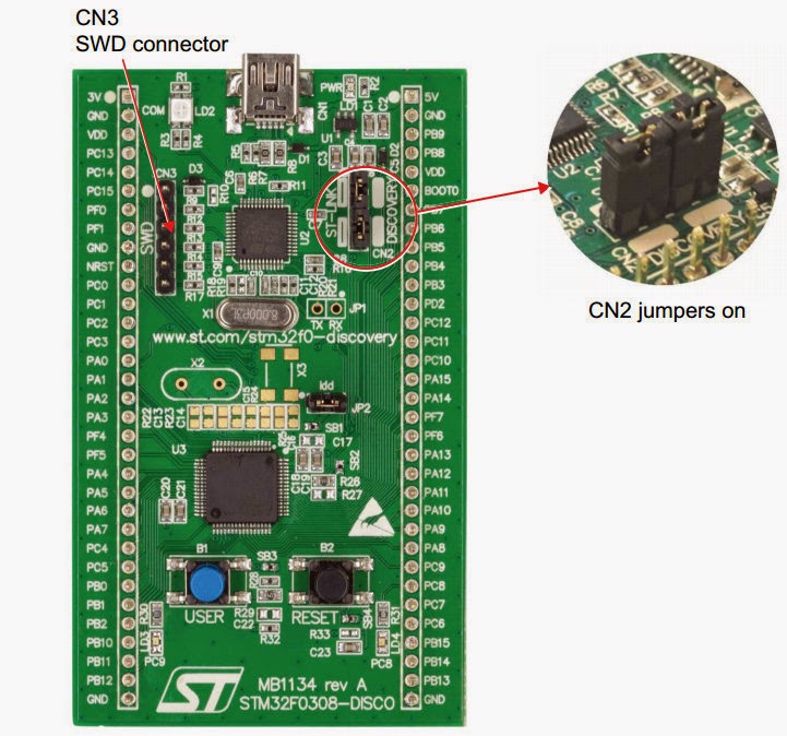
Discovery stm32f1discovery is equipped with 4 pin SWD.  All other discoveries AFAIK are ST-LINK V2 and come with 6 pin SWD.  Remove the jumpers as shown on left to disconnect the on-board SWD control from the CPU (the one that also plugs into your PC's USB; discovery docs) then you can use the SWD connector to pulg it into T6.

Notably, the V1 and V2 also differ in software. and in general the V2 is much more reliable according to openocd references.


4-pin SWD

Schematics

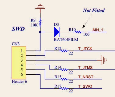
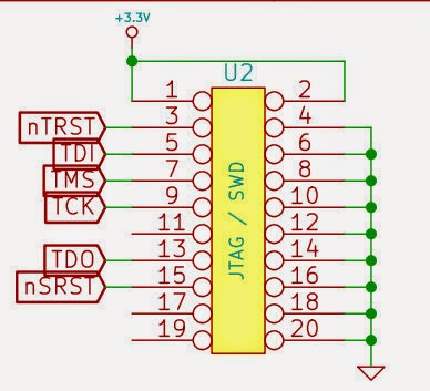
Here are the schematics for 4,6 pin and full 20 pin SWD connector as seen on T6.


Note that SWD lines are also used by JTAG. Through some signaling magic CPUs would cpu obey (switch into) SWD instead of JTAG.


The 4 pin is identical to the first 4 pins on 6-pin connector - handy!.


6-pin SWD
The VDO pin (pin 1 of the connectors) is not used - it is disconnected on discovery boards. I tied it to +3V3 on T6's side.


Connections to T6


T6 20-pin "full" debug connector


I have connected the following:
 U2(T6)    CN3 (DISCO)
+3.3V P1---P1 VDD 
TCK   P9---P2 TCK
GND   P20--P3 GND
TMS   P7---P4 TMS
nSRST P15--P5 NRST
GND   P18--P6 SWO

Also the SWO is not available on F1xx CPU (this is used normally for trace output). This schematics is from ar-t6 .


Here is the final result. Pin #1 is marked with a sqare, left lower row.
I have also cut out small opening for a standard 6-ping header (female) that I have crimped and than hot-glued to the case. So now I can close the T6 and have it ready for flying in no time. Additionally, I found a 12V PS with correct plug and can now power T6 on my desk w/o batteries - this is a bonus and not required.

Let me know.
...sorry for formatting - blogger is a pile of streaming google...and google really stinks recently...


Monday, October 27, 2014

Embedded software with Eclipse, Arm, Stm32fxxx, OpenOCD to develop FlySky FS-T6 trasmitter firmware

This is a very terse dump of my experience of setting up a development environment for developing software for STM32Fxxx series of ARM processors. These CPUs come in a VERY inexpensive "discovery" boards (e.g. STM32F0DISCOVERY,  STM32F3DISCOVERY, STM32F4DISCOVERY) - very fun to toy with (usually $10-20 and no need for any "emulators", "jtags" programmers etc). So this is cheaper then the famous "arduino" and you get a 32bit processor with tons of peripherals. I actually used this to start developing firmware for FlySky-T6 RC transmetter following the fantastic work here.

In order to develop embedded software one usually needs: text editor, build tools, programmer/debugger tools. Here there are in order:
- Eclipse
- gnu arb toolchain
- openocd

The Eclipse is an IDE (Integrated Development Environment) that integrates editor, project management, build, debug documentation in one common, portable, extendable GUI.

The gnu arb tool chain provides compiler/linker/stdlibraries/debugger to produce executable code.

The openocd provides access to hardware. It can communicate with hardware debugger agent and provide flash memory access and debugger server that then can interact with gdb (the gnu tools debugger). An ST-LINK/ST-UTIL (texane or STM versions) can be used instead as well.

Eclipse/GNU/OpenOCD setup

Eclipse:
http://www.eclipse.org/downloads/

this usually ends up a "java" development without CDT ("C/C++"). I have downloaded Eclipse "Luna" .
Install CDT Plugin (skip this if you've donwloaded a CDT-Eclipse):
http://www.eclipse.org/cdt/downloads.php
in the above find correct "p2 repository" link --> Copy to clipboard
in eclipse: Windows->Install New Software->Paste Link
install main CDT + GCC and HW debug
Install GNU ARM Plugin
install "p2 repository":  http://gnuarmeclipse.sourceforge.net/updates
re http://sourceforge.net/projects/gnuarmeclipse/files/Eclipse/updates
Install GCC ARM toolchain (from launchpad):
https://launchpad.net/gcc-arm-embedded/+download
setup for win32 or in debian/ubuntu apt-get install
Creating first project
select "C/C++" perspective - on the right upper, if not there "+" (add) it
file->new C/C++ project select one for your CPU; see below

WARNING - after days of somewhat working debugger I faced gradual dysfunction: 1) eclipse stopbbed being able to interract with openocd in "pipe" mode (ie when it launches oocd itself) - I have switched to running oocd manually. 2) later it decided to gray out (disable) all debug buttons even after successful start and hitting a breakpoint. This was described in this thread:
https://www.eclipse.org/forums/index.php/t/791751/. Solution was to uninstall "GDB Hardware Debug support" (the openocd pluging started to work!).

OpenOCD - Windows

Specific to the ar-t6 firmware:
Notes:
On windows you'd get 2 build errors - can't find "echo" and "make" - solution is to steal them from codesourcery as per http://gnuarmeclipse.livius.net/blog/build-tools-windows/:
http://sourceforge.net/projects/gnuarmeclipse/files/Miscellaneous/Cross%20Build%20Tools.zip/download
but an alternative would be to install gnuwin32 and add them to the path.

Based on similar w/ CodeSourcery:
http://en.radzio.dxp.pl/stm32vldiscovery/programming,with,opensource,toolchain,codesourcery,eclipse.html
http://gnuarmeclipse.livius.net/blog/openocd-install/
http://www.freddiechopin.info/en/download/category/4-openocd
usb drivers for ST-LINK:
http://www.st.com/web/catalog/tools/FM147/SC1887/PF258167
alternatively (not adviced) http://zadig.akeo.ie Options->show all->ST-LINK UpdateDriver

There may be a need to install libusb0 (can't tell if it got installed with zadig or came with ST-LINK installation). Just in case you may want to install it from here:
http://sourceforge.net/projects/libusb-win32/files/latest/download

Then in eclipse: http://gnuarmeclipse.livius.net/blog/openocd-debugging/ but it does not run openocd so had to manually run
"openocd -f stm32f0discovery.cfg -s c:\home\openocd-0.8.0\scripts"

The solution is to change to windows backslashes. Make sure the cmd params are correct as eclipse would not give you any hints as to why it failed to start it.

Other/T6 related


STM32F1xx standard peripheral library
http://www.st.com/web/catalog/tools/FM147/CL1794/SC961/SS1743/LN1734/PF257890
but no need for it as it comes with ARM plugin...

I see occasional communication problems between eclipse (gdb?) and openocd debug server. Killing the openocd process from Task Man restarts system to working condition.
git clone the ar-t6 into your "workspace" directory. the proceed to open project. If you do not know eclipse you will go through world of pain as it is not intuitive. That's okey, it will pass...

The original project builds fine with gnu tools (with some warnings about code sourcery paths) . It contains CMSIS library (arm and stm parts).

One needs to setup openocd "Debug Configuration" as per
http://gnuarmeclipse.livius.net/blog/openocd-debugging/

Also in addition I have setup a special stm32f1-fst6,cfg (saved into openocd/scripts/board)  :

# This is an FlySky T6 base on STM32F100R8
source [find interface/stlink-v2.cfg]
source [find target/stm32f1x_stlink.cfg]
# use hardware reset, connect under reset
reset_config srst_only srst_nogate

That's what goes into "config options" in the "debug" tab of debug configuration :
-f stm32f1-fst6.cfg
Try this from CLI
openocd -f stm32f1-fst6.cfg

It should report the chip id and number of hw breakpoins etc. and then wait for GDB to connect.

Also in the debug configuration that you've set up per "openocd eclipse setup" I had to change the "debug/gdb client setup/executable" to explicitly say "arm-none-eabi-gdb" as the at-t6 project does not seem to define standard "cross-" macros. The debug configuration got committed to github as "ar-t6 Debug.launch" but it's a "Windows" one.

Wednesday, April 20, 2011

Kitesurfing: Leading Edge Blowup Kite Repair

(experimental, ie do not follow)

My Flexifoil Ion3 9m blew up. To add insult to the injury it blew up on the beach, in my hands when I was inverting it to pack and go home. Darn! Looks terrible. I simply think it just got old and tried to quit on me. No such luck, buddy! The quitting I mean, not getting old.

So here is my attempted, DIYig (DIY in garage) revival report. Some things worked, some were messed up. I am yet to try to fly it...


The repair was a two step process: the bladder and the canopy. Since I am lazy by nature I decide not to pull out the bladder completely but just slide it out of the tip. This was possible since the damage was close to the tip.
So here it is, the bladder with a fist-size hole. They say, cut it open and glue a patch from the inside. I say no need to fix a hole by creating another hole.


I removed the air connection from only one strut and rolled the bladder so it does not get in the way.Then I used some sticks to stretch damage area.

I used a bigger-then-palm patch out of an old bladder and put it into the bladder through existing opening (technical term to describe a hole). Just made the patch way oversize so when glued with AquaSeal, the glue would not have a chance to glue the bladder's walls together. Here the black marks the edges of the patch (it's inside the balder). The glue already applied through the hole (I have cut out the original damaged area from the blown-out material).


I have also applied another patch from the outside. I have spread the glue to keep the edges of the outside patch glued to the bladder.

After 12 hours under load, the glue turned yellow. I have not used AquaSeal before so I have not idea if this is OK....It feels flexible and strong.

This is how it looks like cured.

Anyway, the only other problem was that there were small pockets of air left between the patches. But is this a problem really?

This part was relatively easy. The stitching required patience and a lot of ...
Here it is, the top seam opened to make more space for sewing. I had only a fairly thick dacron from my boating days. I have also used the double sided sewing tape 3/4" (the white strips already attached to the edges of the damage. I have decided to put a single band of dacron and sew it in.


In order to help with alignment I first applied a insignia cloth to the outside. This helps keeping the edges together and in good place.

Then I placed the dacron into the double sticky tape. The insignia cloth was a second take idea. I found that the sewing tape is not sticky enough to hold the edges together.


Sewing the seeds of love..ahem...adjusting my flaky walking foot machine is always a challenge, esp when I have not used it for a few years. She's got rusty, so did I.

Four rows of zig-zag from the edge to the edge. I had to rip it out only once when the sail cloth got sewn in. Only once I swear!
Then I got a brilliant idea to strengthen the cloth and put a spinnaker repair tape around the edges. Esthetic's got lost in the process (the tape is white).
But where did the bladder go? I dropped it rolled into the LE shoulder. Kept it nicely out of the way.

Sew him up, doc! I had to get the bladder out. Stretch it and somehow pray I will not sew it in while closing the leading edge.

Here, under (minor) pressure test....It worked!. Just royally miscalculated (read "screw up") one small detail. The edges got quite strong with extra spinnaker tape and with the dacron (see: it is nicely going all the way from edge to edge). But...unfortunately, the dacron I used way thicker then the original cloth and hence I could not fold it. Darn!  This made the repair downright ugly...


the good


This is plausible result. Kite survived nightly pressure test. and looks fine on the outside.


the bad and the ugly

Note the LE deformation. I suspect it could be a result of original damage and/or my sewing. It looks like the circumference is smaller in this area. Perhaps, I should redo the top seam. One day. Perhaps.

Oh, well. I only meant the repair as an experiment....I do not think I'd take it into waves anymore. But on flats or as a learning kite it is still OK.